N132x 32-Channel Digital Input Module
32 digital inputs. Three signal options. Reliable isolated acquisition for distributed I/O systems.
High-density digital input acquisition in a compact module.
Industrial control panels often require dozens of digital input points for switches, sensors, relays, alarms, and machine-status signals. Using multiple low-density modules increases panel space, wiring complexity, and installation time.
The N132x series integrates 32 digital input channels into one compact distributed I/O module. It is designed for use with a compatible N Series fieldbus coupler, such as the BL210 series, to collect, monitor, and transmit field-level digital signals.
Three versions are available for different signal types: N1321 for low-level triggering, N1322 for high-level triggering, and N1323 for dry-contact inputs.
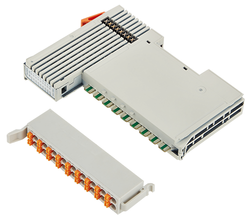
Key Features of the N132x Series
32-Channel High-Density Input
Each N132x module provides 32 digital input channels, identified as DI1 through DI32. The high channel density helps reduce the number of modules required in applications with many switches, sensors, status contacts, and alarm signals.
Three Input Signal Options
Select the model according to the output type of the connected field device.
- N1321: 32-channel low-level-trigger digital input
- N1322: 32-channel high-level-trigger digital input
- N1323: 32-channel dry-contact digital input
2 kVrms Isolation Protection
The digital input section provides 2 kVrms isolation protection. This helps reduce interference between field signals and improves the reliability and stability of signal acquisition in industrial environments.
Individual Channel LED Indication
Each of the 32 digital input channels has a green status indicator. The LED is illuminated when the corresponding input is at logic 1 and turns off when the input is at logic 0, allowing technicians to check field-signal status directly from the module.
The module also includes red power indicators for the 24 V and 3.3 V power states, making power and operating-status checks faster during commissioning and maintenance.
Spring-Cage Wiring Terminals
The spring-cage terminals support solid, stranded, and fine-stranded conductors. Supported conductor sizes range from 0.3 to 2.5 mm² or AWG 22 to AWG 14.
The recommended stripping length is 8 to 9 mm. Each spring-cage connection is intended for one conductor. Shielded cable should be used in accordance with the installation requirements.
Internal Bus Communication and Power
Communication between the fieldbus coupler and the I/O module, together with module system power, is provided through the internal bus. The bus uses eight gold-plated data contacts with a self-cleaning action during connection.
Compact DIN-Rail Installation
The N132x mounts on a standard DIN-35 rail in accordance with IEC 60715. Modules are installed next to the fieldbus coupler from left to right, creating a compact distributed I/O station without requiring modules to be grouped by type.
Choose the Correct N132x Model
| Model |
Channels |
Input Type |
Common Terminal |
| N1321 |
32 |
Low-level trigger |
Connected to power supply positive |
| N1322 |
32 |
High-level trigger |
Connected to 0 VDC |
| N1323 |
32 |
Dry contact |
Logic state determined by contact open or closed |
Input Logic
N1321 Low-Level-Trigger Input
- Logic 1: +15 to +30 VDC
- Logic 0: -3 to +5 VDC
- Common terminal: Connected to the positive side of the power supply
N1322 High-Level-Trigger Input
- Logic 1: +15 to +30 VDC
- Logic 0: -3 to +5 VDC
- Common terminal: Connected to 0 VDC
N1323 Dry-Contact Input
- Logic 1: Input terminal shorted to the common terminal
- Logic 0: Input terminal disconnected from the common terminal
Designed for Industrial Applications
Factory Automation
Collect operating, alarm, limit-switch, and equipment-status signals from production machines and automated manufacturing lines.
Control Panels
Consolidate up to 32 digital input points in a compact module to reduce panel space and simplify distributed signal acquisition.
Equipment Monitoring
Monitor relay contacts, switches, alarms, interlocks, and equipment operating states through a compatible distributed I/O coupler.
Industrial System Integration
Combine the N132x with other compatible N Series I/O modules in the same fieldbus node. Modules may be arranged as required by the application and do not need to be grouped according to module type.
Technical Specifications
| Product type |
32-channel digital input module |
| Models |
N1321, N1322, N1323 |
| Number of channels |
32 digital inputs |
| System power |
5 VDC through the internal bus |
| Current consumption |
21 mA at 5 VDC |
| Isolation protection |
2 kVrms |
| Conductor size |
0.3–2.5 mm² / AWG 22–14 |
| Stripping length |
8–9 mm / 0.33 in |
| Operating temperature |
-20°C to +55°C |
| Storage temperature |
-40°C to +70°C |
| Relative humidity |
5% to 95%, non-condensing |
| Operating altitude |
0–2,000 m |
| Protection rating |
IP20 |
| Dimensions |
28.4 × 104.6 × 74.9 mm |
| Weight |
122.2 g |
| Mounting |
DIN-35 rail |
| EMC |
IEC 61000-4-2 ESD Level 2;
IEC 61000-4-5 Surge Level 2 |
Installation Notes
Install the fieldbus coupler and I/O modules on an IEC 60715-compliant DIN-35 rail. Starting from the coupler, install the I/O modules next to one another from left to right. Fit an end cover after the final module to prevent the metal contacts from remaining exposed.
Before inserting a module, make sure its DIN-rail latch is unlocked and that the module guide is aligned with the groove of the coupler or adjacent I/O module. Press the module into position and lock the rail latch after installation.
To remove a module, use a flat-head screwdriver or similar tool to lift the DIN-rail latch, and then pull the module away from the rail. Removing a module disconnects its data and power-jumper contacts.
The N132x series must be used with a compatible distributed I/O fieldbus coupler. Select N1321, N1322, or N1323 according to the required field-signal type and wiring method.
Documentation and Product Selection
For complete terminal definitions, wiring diagrams, installation instructions, and model selection information, please refer to the N132x user manual and the Distributed I/O Selection Guide .


